The Networking Brain Dump, Part 1: Layers 1-4
So I've been sitting on a few hundred pages of networking notes for a while now. The kind you write when you're trying to actually understand something, not just get through an exam. The problem is nobody wants to read a few hundred pages of notes, and I don't always have time to turn them into something readable myself. So this series is what happens when you hand those notes to Claude, ChatGPT, and Gemini with specific instructions on what to include and how to write it.
This isn't a beginner's tutorial and it isn't an expert's reference. It's somewhere in between - the resource I wish had existed when I was learning this. No TLS, IPSec, or security architecture yet; that's a separate series. What this does cover, across six parts, is the full stack from how bits move on a wire to how BGP keeps the internet from collapsing. By the end you'll have seen it all in one place.
Part 1 is layers 1 through 4 of the OSI model. If you already know what a 3-way handshake is, some of this is review. That's fine. There's enough beyond the basics to make it worth reading either way.
The OSI Model
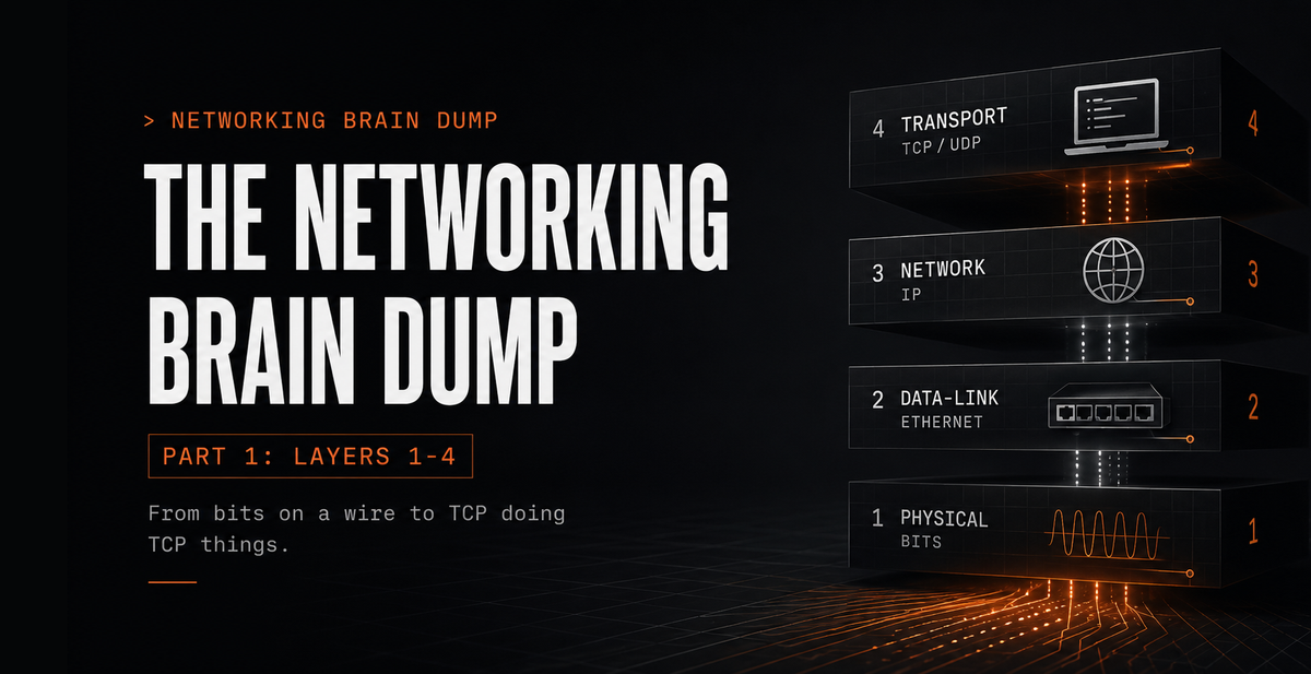
The OSI model is a framework for understanding how network communication works. Seven layers, each with a specific job, each providing services to the layer above while depending on the layer below. The design intent is that each layer only has to care about its own responsibilities, not what's happening two layers up or down.
The seven layers from top to bottom: Application, Presentation, Session, Transport, Network, Data-Link, Physical. "All People Seem To Need Data Processing" works going down. Bottom-up it's "Please Do Not Throw Sausage Pizza Away." Either works; pick one.
The thing to hold onto before going layer by layer: upper layers care about what the data is. Lower layers care about moving it. Upper layers are closer to the user and the application. Lower layers are closer to the physical medium. When data travels down the stack to be sent, each layer wraps it in its own header (and sometimes a trailer) before passing it further down. This is encapsulation. On the receiving end, each layer strips its own header as data moves back up. This is decapsulation. The payload arrives at the application unchanged.
This post covers layers 1 through 4. Layers 5 through 7 are in Part 2.
Layer 1: Physical
The Physical layer takes whatever the Data-Link layer hands it and puts it on the wire as a stream of bits. No structure, no addresses. It encodes those bits as voltage changes on copper, light pulses in fiber, or radio waves in the air, and transmits them across whatever physical medium is in use.
Encoding
NRZ (Non-Return to Zero): High voltage is a 1, low voltage is a 0. Simple. The problem is that long runs of the same bit cause timing drift at the receiver, since there are no transitions to synchronize on.
Manchester encoding: Every bit period has a voltage transition at its midpoint. A falling transition represents a 0, a rising transition represents a 1. The constant mid-bit transitions keep the receiver's clock synchronized, which matters more as distances increase and timing drift becomes a real problem.
Throughput and Goodput
Throughput is the actual measured rate of data across a link. Goodput is throughput minus overhead. If a 100 Mbps link is carrying 20 Mbps of headers, retransmissions, and protocol control traffic, goodput is 80 Mbps. Throughput is what the link does. Goodput is what the application actually sees.
Physical Media
Copper
Coaxial cable is the ancestor of modern wired networking. It has largely been replaced by UTP (Unshielded Twisted Pair), which runs at higher speeds and costs less. The twisted pairs are doing real work: interference picked up on one wire in a pair is canceled by the equal and opposite interference picked up on the other, which eliminates most EMI and RFI without requiring shielding.
Cable types by use:
- Straight-through: Connects different device types. A PC to a switch, a switch to a router.
- Crossover: Connects same device types. Switch to switch, PC to PC. Modern switches handle this automatically via auto-MDI/MDIX, but the distinction still appears in legacy hardware and on exams.
- Rollover: Connects a workstation's serial port to a router's console port for out-of-band management. Requires a USB adapter on anything made in the last decade.
Fiber optic
Light pulses through glass rather than electrical signals through copper. No EMI, no RFI. Typically deployed as a pair of fibers, one for transmit and one for receive, enabling full-duplex communication.
- Single-mode fiber (SMF): Core diameter around 9 microns. Uses a laser. Supports distances up to roughly 100km. Used for WAN links and long-haul data center interconnects.
- Multimode fiber (MMF): Wider core, around 50 to 62.5 microns. Often uses an LED. Good for runs up to about 2km. The standard choice for shorter runs within buildings or between nearby racks.
Wireless
Radio and microwave frequencies. Wi-Fi, Bluetooth, cellular. No cable, but the medium is shared. More devices competing for the same spectrum means more contention and more potential interference.
Layer 2: Data-Link
The Data-Link layer gives structure to the raw bit stream below it and provides a reliable handoff point for the network layer above. It handles three things: framing (packaging data into discrete units with headers and trailers), media access control (deciding who transmits when), and error detection (catching corrupted frames before they travel further up the stack).
Addressing at this layer uses MAC addresses, 48-bit hardware identifiers assigned to each network interface, written in hex like AA:BB:CC:DD:EE:FF. Designed to be globally unique. Can be changed in software, but the intent is one address per physical interface.
Duplex
Half-duplex: One direction at a time. Devices take turns. Collisions are possible.
Full-duplex: Both directions simultaneously. Each side has a dedicated transmit and receive path. No collisions are possible. Essentially all modern wired Ethernet operates this way.
CSMA/CD and CSMA/CA
These protocols govern access to shared media and only apply in half-duplex environments.
CSMA/CD (Collision Detection) was used in legacy half-duplex wired Ethernet. Before transmitting, a device checks whether the channel is clear. If two devices transmit simultaneously anyway, both detect the collision, stop, wait a random backoff period, and retry. With full-duplex Ethernet this entire mechanism is unnecessary.
CSMA/CA (Collision Avoidance) is used in wireless networking. A wireless device can't easily detect its own transmissions colliding with others mid-air, so it avoids collisions proactively: check that the channel is idle, wait an additional random interval, then transmit.
Ethernet's Two Sublayers: LLC and MAC
Ethernet's Data-Link implementation is divided into two sublayers:
LLC (Logical Link Control): The upper sublayer, defined by IEEE 802.2. It provides the interface between the Data-Link layer and the Network layer above. Handles flow control and error notification between layers.
MAC (Media Access Control): The lower sublayer, implemented in NIC hardware. Two responsibilities:
Data encapsulation: Takes the Layer 3 packet and wraps it in an Ethernet frame. The frame header contains source and destination MAC addresses. The trailer contains a CRC (Cyclic Redundancy Check), a checksum computed over the frame contents. When a device receives a frame, it recomputes the CRC and compares it to the trailer. A mismatch means the frame was corrupted in transit and it gets discarded.
Media access: Works with the Physical layer to put frames on the medium and pull them off.
Ethernet Switches
A switch learns the network by watching traffic. Every incoming frame has a source MAC address. The switch records that address and the port the frame arrived on in the CAM table (Content Addressable Memory, also called the MAC address table). When a frame arrives destined for a MAC address the switch has already seen, it forwards out only the correct port. When the destination is unknown, it floods the frame out every port in the same VLAN except the one it arrived on.
show mac address-table
On older Cisco IOS:
show cam dynamic
Forwarding methods:
Store and Forward: The switch buffers the complete incoming frame, verifies the CRC, then forwards. Catches corrupted frames before they propagate. Adds latency proportional to frame size.
Cut-Through: The switch starts forwarding as soon as it reads the destination MAC address, before the full frame has arrived. Two variants:
- Fast-Forward: Forwarding starts immediately after the destination MAC is read. Lowest possible latency, no error checking.
- Fragment-Free: Waits for the first 64 bytes before forwarding. The minimum valid Ethernet frame size is 64 bytes, and collision-induced corruption appears within those first 64 bytes. Waiting that long catches collision fragments without waiting for the entire frame. A middle ground between the other two methods.
ARP
Before a device can send a frame, it needs the destination's MAC address. If it doesn't have it, ARP (Address Resolution Protocol) finds it. The device broadcasts to the entire local network: "Who has IP address X? Reply with your MAC address." The device with that IP responds directly. Both sides cache the result in their ARP tables.
arp -a      # View the ARP cache
arp -d *    # Clear the ARP cache
IPv6 replaces ARP with Neighbor Discovery, specifically NS/NA messages (Neighbor Solicitation / Neighbor Advertisement). Instead of a broadcast to everyone, the querying device sends a Neighbor Solicitation to a solicited-node multicast address derived from the target's IPv6 address. Only the target listens on that address, so only it receives the solicitation and replies with a Neighbor Advertisement containing its MAC address. Far more efficient than broadcasting to every device on the segment.
Layer 3: Network
The Network layer handles communication between devices on different networks. Layer 2 gets a frame from one port to another on the same network. Layer 3 gets a packet from a host in one city to a host in another, across multiple networks and routing devices, using IP addresses for logical addressing.
Three things define how IP behaves:
Best-effort delivery: IP does not guarantee that a packet arrives. A packet lost somewhere in the network is gone. IP doesn't know, doesn't retry. That's the transport layer's problem, if reliability matters at all.
Connectionless: IP doesn't set up a path between source and destination before sending. Each packet is routed independently based on current network state. Two packets from the same flow can take completely different paths and arrive out of order.
Media independent: IP runs over anything beneath it. Copper, fiber, wireless. What it does receive from the Data-Link layer is the MTU (Maximum Transmission Unit), the largest frame size the physical medium supports. If an IP packet is larger than the MTU, the Network layer fragments it into smaller pieces that each fit within the limit. The destination reassembles them. IPv6 handles this differently: routers do not fragment packets in transit, so the sender has to size packets appropriately using path MTU discovery. Path MTU discovery works by the sender sending packets with a "Don't Fragment" aka "DF" bit enabled; if a packet is too large for a router, the router drops it and sends back an ICMP error message reporting its supported size(if ICMP is blocked, you end up with an MTU black hole causing connections to continuously time out). The sender then shrinks its packets to match that reported size and retries until the data successfully reaches its destination.
Layer 4: Transport
The Transport layer moves data between applications on different hosts. Not just between hosts, but between specific processes running on those hosts. Port numbers live here. When a browser connects to a web server, the TCP segment carries the browser's source port and the server's destination port 443. The combination of source IP, source port, destination IP, and destination port is a socket pair, and it uniquely identifies a single connection. This is how one machine maintains thousands of simultaneous connections.
netstat # Lists active TCP connections on the host
Two protocols at this layer. They make different tradeoffs.
TCP
TCP (Transmission Control Protocol) is used when losing data is not acceptable. It establishes a connection before sending anything, tracks every byte it sends, retransmits anything that goes unacknowledged, and prevents the receiver from being overwhelmed. All of that costs overhead.
The 3-way handshake:
- Client sends SYN with its starting sequence number.
- Server responds with SYN-ACK, acknowledging the client's sequence number and sending its own.
- Client sends ACK.
Connection established. Normal teardown is FIN, ACK, FIN, ACK: both sides signal they're done and acknowledge the other's signal. If a connection needs to die immediately, either side sends RST and it's over without the graceful sequence.
Reliable delivery: Every segment gets a sequence number. If an ACK doesn't arrive within the retransmission timeout, the sender retransmits. Nothing is silently dropped from TCP's perspective.
Ordered delivery: Sequence numbers let the receiver reassemble segments in the correct order regardless of how they arrived. Out-of-order delivery is common in real networks.
Flow control: TCP prevents a fast sender from flooding a slow receiver's buffers. The mechanism is the receive window.
TCP Windowing
During the handshake, both sides advertise their window size: the maximum number of unacknowledged bytes they'll allow in flight at any given time. The sender transmits up to that limit and waits for acknowledgments before sending more. Starting sequence numbers are chosen randomly - predictable sequence numbers are a known attack surface.
When a segment is lost, the receiver keeps acknowledging the next byte it expected to receive. The sender eventually detects the gap through duplicate ACKs or, if that signal is not enough, a retransmission timeout, then retransmits the missing data. The receiver may also advertise a reduced window size if its buffer is filling, but that window is about receiver capacity, not the primary signal that packet loss occurred.
Example: window size is 3000 bytes, segments are 1500 bytes.
- Segment 1 (bytes 1-1500): received fine.
- Segment 2 (bytes 1501-3000): lost in transit.
- Receiver keeps sending ACK 1501, because byte 1501 is still the next byte it expected.
- If later data arrives out of order, the repeated ACK 1501s become duplicate ACKs, which tell the sender there is a gap.
- If the receiver's buffer starts filling while waiting for the missing data, it may also advertise a smaller receive window.
Sliding Windows
Basic windowing is stop-and-wait: fill the window, stop, wait for all ACKs, then fill it again. Sliding windows improves on this. The receiver sends an ACK for each segment as it arrives, rather than waiting for the full window to be filled. The sender slides the window forward with each ACK and keeps the pipeline full without pausing.
With a 1000-byte window and 100-byte segments: sender transmits 100 bytes, gets an ACK, window slides 100 bytes forward, sender transmits the next 100 bytes. The link stays utilized continuously.
TCP Slow Start
When a TCP connection begins, or recovers from packet loss, it doesn't immediately transmit at the full window size. It ramps up gradually:
- Start by sending a small number of segments rather than immediately filling the path (e.g., 2)
- For each ACK received, double the number: 2, 4, 8, 16...
- Once the slow start threshold (ssthresh) is reached, growth becomes linear.
When a packet goes unacknowledged, TCP treats it as a congestion signal and resets to the bottom of this ramp.
TCP Global Synchronization is the failure mode that happens when a router's output queue fills completely. The router begins tail dropping: discarding any new packet that arrives because there's no buffer space. Every TCP connection that had packets in that queue detects the loss simultaneously. They all back off simultaneously. The link drops to near-zero utilization. Then all connections ramp back up together, hit the queue at the same time, trigger another round of tail drops, and the cycle repeats indefinitely.
RED (Random Early Detection) breaks this. As the queue starts filling, before it's completely full, RED begins randomly dropping a small fraction of packets. Not all connections get hit at once. Different connections go into slow start at different times, the link stays busy, and the global synchronization problem disappears.
PSH and URG Flags
Beyond SYN, ACK, FIN, and RST:
PSH (Push): Tells the receiver to deliver data to the application immediately rather than waiting to fill a buffer. Matters in interactive sessions like SSH where every keystroke needs to be processed as it arrives rather than batched.
URG (Urgent): Marks the segment as urgent, telling the receiver to prioritize processing it over buffered data. Less common in modern applications but still part of the specification.
UDP
UDP (User Datagram Protocol) drops all of TCP's guarantees in exchange for simplicity and speed. It's connectionless (no handshake), unreliable (no ACKs, no retransmission), unordered (no sequence numbers), has no flow control, and maintains no connection state between sends. A UDP segment goes out and whatever happens to it happens.
For a specific set of use cases, this is exactly right:
Streaming video: A dropped frame means a brief artifact. A retransmission of a frame from three seconds ago is useless by the time it arrives.
DNS queries: Small, fast. If no response arrives, retry. Running TCP's handshake for a query this lightweight would cost more time than it saves.
VoIP and real-time audio/video: Latency kills call quality. A moment of static beats freezing while waiting on a retransmission.
Online gaming: Position updates need to arrive now. Where someone was 200ms ago has no value.
The pattern: UDP is correct when low latency matters more than guaranteed delivery, or when the application handles reliability at a higher layer. When neither condition applies, TCP is almost always the better choice.
Part 2 covers layers 5 through 7, DNS, HTTP, email protocols, FTP, static and dynamic routing, DHCP for IPv4 and IPv6, and subnetting.
Part 1 of 6 in the Networking Brain Dump series.