The Networking Brain Dump, Part 3: VLANs, STP & EtherChannel
Part 3 of 6. Parts 1 and 2 covered the OSI model, all seven layers, and routing fundamentals. This one stays at Layer 2 and goes deep into how switched networks are designed, protected from themselves, and optimized.
VLANs
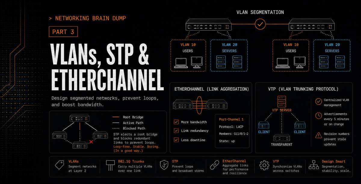
A VLAN (Virtual LAN) is a logical partition of a Layer 2 network. VLANs are created within switches and used to break up broadcast domains: traffic generated in one VLAN stays in that VLAN. It does not leak into others.
The practical effect is that devices in different VLANs cannot communicate directly, even if they're connected to the same physical switch. Packets can only cross VLAN boundaries through a router or a Layer 3 interface on a Layer 3 switch. This gives you network segmentation without buying separate physical hardware for every group.
Inter-VLAN Routing
Three ways to route between VLANs:
Legacy inter-VLAN routing: Each VLAN gets its own dedicated physical interface on the router. Simple but wasteful. If you have eight VLANs you need eight router ports, which is why nobody does this at scale.
Router-on-a-stick: A single physical router interface is divided into software-based subinterfaces, each assigned to a different VLAN. All inter-VLAN traffic flows through one physical link. The router tags and untags traffic appropriately as it passes through.
Layer 3 switching with SVIs (Switched Virtual Interfaces): A Layer 3 switch handles routing directly in hardware. Each VLAN gets an SVI, which acts as its default gateway. No external router needed. Faster than router-on-a-stick and the standard choice for enterprise campus networks.
VLAN Types
Default VLAN: VLAN 1. Every switch port belongs to this VLAN out of the box. You can't delete VLAN 1, but it's common practice to move everything off it and use it only for legacy compatibility.
Data VLAN: Created for specific groups of users or devices. This is where user-generated traffic lives. Each department, each tier of an application, whatever segmentation makes sense for the environment.
Native VLAN: Carries untagged traffic on a trunk. Any frame that arrives on a trunk port without an 802.1Q tag is assumed to belong to the native VLAN. Default is VLAN 1. Mismatched native VLANs between two switches on the same trunk is a real problem: traffic from a data VLAN on one switch can end up on the native VLAN of the other switch. Keep them consistent.
Management VLAN: Carries network management traffic: SSH, SNMP, Syslog. Also defaults to VLAN 1, which is another reason to change both the native and management VLAN assignments away from 1. You don't want management traffic mixing with user data.
Voice VLAN: Dedicated to IP telephony traffic. Voice requires guaranteed bandwidth, low delay, and priority over other traffic types to avoid jitter and dropped calls. A voice VLAN gives QoS policies somewhere to latch onto.
VLAN Trunks
A trunk is a point-to-point link that carries traffic from multiple VLANs simultaneously. Trunk links are typically configured between switches, or between a switch and a router running inter-VLAN routing. The trunk doesn't belong to any single VLAN; it carries all of them.
Trunking is done using IEEE 802.1Q, which adds a 4-byte tag to each Ethernet frame identifying which VLAN it belongs to. Switches on both ends of the trunk read this tag to know where to send the frame. The exception is native VLAN traffic, which is sent untagged.
VTP
VTP (VLAN Trunking Protocol) lets a network administrator manage VLANs from a central point. Instead of configuring every switch individually, changes made on a VTP server propagate automatically to all other VTP-enabled switches in the same domain.
The VTP domain is a logical grouping of switches that share VLAN information. Every switch in the domain sends VTP advertisements out its trunk ports to a reserved Layer 2 multicast address. Neighboring switches receive those advertisements and update their VLAN databases accordingly.
VTP Modes
Server: The authoritative mode. VLANs are created, deleted, and renamed on server-mode switches, and those changes replicate to the entire domain. VLAN information is stored in NVRAM and survives a reboot.
Client: Receives and applies VLAN updates from servers but cannot make changes itself. In VTP versions 1 and 2, VLAN information is only held in memory, not NVRAM. After a reboot, the switch needs to relearn the VLAN database from a VTP server in the same domain.
Transparent: Doesn't participate in VTP synchronization at all, but will forward VTP advertisements it receives to other switches. VLANs created on a transparent switch are local to that switch only and not shared with the domain.
VTP Configuration Revision Number
Every VTP update carries a configuration revision number that increments with each change. When a switch receives a VTP advertisement, it compares the revision number to its own. If the incoming number is higher, it assumes the advertisement is more current and updates its database to match.
This creates a significant risk when adding a switch to an existing network. If that switch has a higher revision number than the servers in the domain, possibly because it was previously used in another network, it will overwrite the entire domain's VLAN database with its own. Switches would lose VLANs from the shared VLAN database, which can break access ports, trunks, and any traffic depending on those VLANs.
To reset a switch's revision number before connecting it to a production network: change the VTP domain name to something else, then change it back. Or set the switch to transparent mode and back to client or server mode. Either resets the counter to zero.
VTP Advertisement Types
Summary advertisements: Sent every five minutes and whenever a VLAN change occurs. Contains the VTP domain name and the current configuration revision number. This is how switches know whether they're up to date.
Advertisement requests: Sent by a switch when it receives a summary advertisement with a higher revision number than its own. It's asking for the full current VLAN database.
Subset advertisements: The actual response to an advertisement request. Contains the complete VLAN information including any recent changes.
DTP
DTP (Dynamic Trunking Protocol) is a Cisco proprietary protocol that allows two connected switch interfaces to automatically negotiate whether to operate as a trunk or an access port.
The interface modes:
switchport mode access: Forces the port into access mode. No trunking, no negotiation.
switchport mode trunk: Forces the port into trunk mode. Will send DTP frames but doesn't require the neighbor to respond.
switchport mode dynamic auto: Passive. Will form a trunk if the neighboring port is set to trunk or desirable. Two auto ports facing each other will never form a trunk.
switchport mode dynamic desirable: Active. Initiates negotiation and forms a trunk if the neighbor is trunk, desirable, or dynamic auto.
switchport nonegotiate: Disables DTP frame generation entirely. Use this on trunk ports connected to non-Cisco devices or when you want to prevent any negotiation from happening.
Spanning Tree Protocol
If you connect multiple switches together for redundancy, you've created Layer 2 loops. Layer 2 has no TTL mechanism. A broadcast frame caught in a loop between switches will circulate forever, doubling in copies with each pass, consuming all available bandwidth and eventually crashing every device on the network. This is a broadcast storm.
Three problems STP is solving:
Broadcast storms: Redundant paths between switches allow broadcasts to loop indefinitely. STP blocks the redundant path so the loop can't form.
Multiple frame transmission: When broadcast storms occur, copies of the same frame flood every connected device repeatedly. End devices receive the same frame dozens or hundreds of times.
MAC database instability: The same MAC address appears on multiple switch ports simultaneously as frames loop between switches. The CAM table fills with contradictory entries and becomes unreliable.
STP resolves all three by putting specific ports into a blocking state. Blocked ports receive BPDUs but don't forward traffic. If the active path fails, blocked ports can be activated to restore connectivity.
BPDUs
Switches exchange BPDUs (Bridge Protocol Data Units) every two seconds (the hello timer). Two types:
Configuration BPDUs: Used to calculate and maintain the spanning tree topology. This is the continuous heartbeat of STP.
TCN BPDUs (Topology Change Notifications): Sent when a port transitions state, notifying the rest of the network that the topology has changed and CAM tables need to be flushed.
STP Operation: Three Steps
Step 1: Elect a Root Bridge. All switches in the broadcast domain elect one switch as the root. The root bridge is the reference point from which all path costs are calculated. Every port on the root bridge is a designated port and remains in forwarding state.
Election is based on Bridge ID (BID), which combines a configurable priority value (default 32768) with the switch's MAC address. The switch with the lowest BID wins. If priorities are equal, the lowest MAC address breaks the tie.
Step 2: Elect a Root Port on every non-root switch. Each non-root switch identifies one port as its root port: the port with the lowest-cost path back to the root bridge. That port forwards traffic toward the root.
Tiebreakers, in order:
- Lowest path cost to the root bridge.
- If costs are equal, the path through the neighbor with the lower BID wins.
- If multiple ports connect to the same neighbor, the port connected to the lowest PID (Port ID, which is port priority plus port number) on the other end wins.
Step 3: Elect a Designated Port on each network segment. For every link segment in the network, one port is elected as the designated port and placed in forwarding state. After root ports are selected, the same cost and BID tiebreaker logic determines which port is designated for each segment. Any port that is neither a root port nor a designated port becomes a blocking port.
PVST+
PVST+ (Per-VLAN Spanning Tree Plus) is Cisco's default STP mode. Rather than running a single spanning tree instance for the entire network, PVST+ runs a separate instance for each configured VLAN. This allows different VLANs to have different root bridges and different blocked ports, which means unused links in one VLAN can carry traffic for another. It's a way to load-balance across redundant links that a single STP instance would leave idle.
RSTP
RSTP (Rapid Spanning Tree Protocol) speeds up the convergence process. Standard STP can take 30 to 50 seconds to move a port from blocking to forwarding after a topology change. RSTP cuts that dramatically.
RSTP removes the listening state from the port transition sequence. Ports go from blocking (now called the 'discarding' state) directly to learning, then to forwarding. RSTP also introduces new port roles and uses a more active handshake mechanism between switches rather than relying entirely on timers.
STP Enhancements
PortFast: Configured on ports connected to end devices (workstations, servers, printers). A PortFast port skips the listening and learning states and goes directly from blocking to forwarding. It also suppresses TCN BPDUs when the port goes up or down, which prevents the entire network from flushing its MAC tables every time a single workstation reconnects. PortFast should only be enabled on ports connected to end devices, not other switches. A switch connected to a PortFast port creates a loop before STP has a chance to react.
BPDU Guard: Configured alongside PortFast. If a PortFast-enabled port receives a BPDU (which means something is sending STP traffic, and therefore probably a switch), BPDU Guard immediately puts the port into err-disabled state. The port shuts down rather than allowing a potential loop to form. It requires manual intervention or a configured err-disable recovery timer to bring the port back up.
BPDU Filter: Prevents a port from sending or receiving BPDUs. The distinction from BPDU Guard matters: if BPDU Filter is enabled on a port that also has BPDU Guard configured, BPDU Guard cannot do its job because no BPDUs are being received to trigger it. A port with BPDU Filter enabled is essentially outside of STP's awareness, which means loops can form on it silently. Be deliberate about where you use this.
Root Guard: Prevents a port from becoming a root port. If a switch receives a superior BPDU on a Root Guard-enabled port, the port is put into a root-inconsistent state and stops forwarding. This prevents a rogue or misconfigured switch from taking over as root bridge, which would force a topology recalculation and potentially reroute traffic through an unintended path.
CST, PVST, and MST
CST (Common Spanning Tree): One spanning tree instance for all VLANs. Simple, but all VLANs share the same topology regardless of whether it's optimal for any of them.
PVST/PVST+: One spanning tree instance per VLAN. Full control over topology per VLAN, but maintaining a separate instance for every VLAN has overhead that scales poorly in large networks.
MST (Multiple Spanning Tree): A middle ground. VLANs are mapped to MST instances (MSTIs), and each instance runs its own spanning tree. Multiple VLANs that would naturally have the same topology are grouped into the same instance, reducing the number of separate trees the network has to maintain. From the perspective of switches outside the MST region, the entire region looks like a single logical switch or subtree. The internal MST instances stay inside the region; outside switches only see the region through the common spanning tree view.
EtherChannel
EtherChannel bundles multiple physical links between two switches into a single logical interface. From STP's perspective, it's one link. From a throughput perspective, traffic is distributed across all the physical member links. STP operates on the EtherChannel bundle as a whole, not on the individual member interfaces.
Two negotiation protocols:
PAgP
PAgP (Port Aggregation Protocol) is Cisco proprietary.
Auto: Passive. The port responds to PAgP packets it receives but does not initiate negotiation. Two auto ports facing each other will not form a channel.
Desirable: Active. The port initiates negotiation by sending PAgP packets. Forms a channel if the neighbor is auto or desirable.
On: Forces the interface into the channel without any PAgP negotiation. Both sides must be set to on, and they must be compatible.
Non-silent: An optional keyword for auto and desirable modes. By default, PAgP operates in silent mode, which means it will bring up the EtherChannel even if no PAgP packets are received from the other side. Non-silent mode requires bidirectional confirmation before the channel comes up. This prevents Layer 2 loops from forming on unidirectional links, but it takes longer to establish the channel.
LACP
LACP (Link Aggregation Control Protocol) was originally defined under IEEE 802.3ad and is now part of IEEE 802.1AX. Not proprietary, meaning it works between equipment from different vendors.
Passive: Waits for LACP packets before responding. Does not initiate negotiation.
Active: Initiates negotiation by sending LACP packets.
On: Forces the channel without LACP negotiation. Same caveat as PAgP on mode: both sides must match.
LACP Additional Configuration
LACP Fast: The original LACP standard sends keepalive packets every 30 seconds. A link is declared failed if three consecutive packets are missed, so failure detection takes up to 90 seconds. LACP Fast changes the interval to 1 second and detection to 3 seconds. Enable it with:
interface <member-interface>
 lacp rate fast
Configure the rate consistently on both sides when possible. The exact behavior can be platform-dependent, but the clean design is to avoid mixed fast/slow expectations across the same bundle (mismatches can prevent the channel from forming in many platforms).
Minimum links (port-channel min-links): Configured on the port-channel interface. Sets a minimum number of member links that must be active before the port-channel itself comes up. If active members drop below the threshold, the port-channel goes down rather than forwarding traffic over an insufficient number of links.
Maximum bundle (lacp max-bundle): Sets the maximum number of active member interfaces in the bundle. You can configure more physical links than the maximum; the extras sit in hot standby and activate if an active member fails. For predictable results, this should be configured identically on both switches in the Port Channel. Though, the switch with the lower LACP System Priority (aka 'master' switch) will ultimately choose which specific physical ports are selected for the bundle if a tie-break is needed.
Since the hash function used for load balancing is binary, bundle sizes should be powers of two (2, 4, 8). A 3-link EtherChannel won't distribute traffic as evenly as a 2-link or 4-link bundle because the hash outputs don't map cleanly onto three links.
LACP system priority (lacp system-priority): Determines which switch is the master for the port channel. The master decides which member interfaces are active when more links are configured than the max-bundle limit. Lower priority wins. If priorities match, the switch with the lower MAC address becomes the master.
lacp system-priority <value>
LACP interface priority (lacp port-priority): Configured per member interface. When the master switch needs to choose which interfaces are active versus standby, lower port priority wins. If two interfaces have identical priority values, the one with the lower interface number wins.
interface <member-interface>
 lacp port-priority <value>
EtherChannel Load Balancing
Traffic across an EtherChannel is not distributed on a round-robin per-packet basis. Instead, a hash is computed from fields in the packet header, and the result maps the packet to a specific member link. The same flow always takes the same link. This preserves packet ordering within a flow while still spreading different flows across the bundle.
Common Cisco EtherChannel hash inputs include:
| Input Code | Hash Basis |
|---|---|
dst-ip |
Destination IP address |
dst-mac |
Destination MAC address |
src-dst-ip |
Source and destination IP |
src-dst-mac |
Source and destination MAC |
src-ip |
Source IP address |
src-mac |
Source MAC address |
src-port |
Source TCP/UDP port (platform-dependent) |
dst-port |
Destination TCP/UDP port (platform-dependent) |
src-dst-port |
Source and destination port (platform-dependent) |
Configure it globally:
port-channel load-balance <method>
Hash input selection matters. If an EtherChannel connects to a router, using MAC address as the hash input is a bad choice: the router's MAC address doesn't change, so all traffic from that router hashes to the same member link regardless of how many links are in the bundle. Source/destination IP or TCP/UDP port-based hashing gives better distribution in that scenario.
Because the hash function is binary, the number of active member links should be a power of two. A 3-port bundle will not distribute traffic as evenly as a 2-port or 4-port bundle. If the distribution across member links is uneven and you can't change the bundle size, adjusting the hash method is the other lever available.
Part 4 covers EIGRP and OSPF: how routers build neighbor relationships, how they calculate paths, and everything that can go wrong in the process.
Part 3 of 6 in the Networking Brain Dump series.