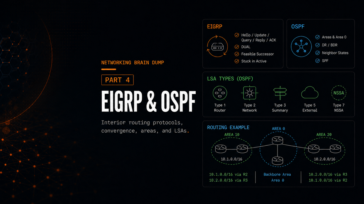
The Networking Brain Dump, Part 4: EIGRP & OSPF
Part 4 of 6. Parts 1 through 3 covered the OSI model, application protocols, routing fundamentals, and Layer 2 switching. This part goes deep into the two most common interior routing protocols. There's a lot here. Take it in sections.
EIGRP
EIGRP (Enhanced Interior Gateway Routing Protocol) is Cisco's distance-vector routing protocol. It operates directly over IP using protocol number 88, not over TCP or UDP. Its administrative distance is 90 for internal routes, 5 for EIGRP summary routes, and 170 for external routes redistributed into EIGRP.
It's classified as a distance-vector protocol, but it behaves quite differently from older ones like RIP. It doesn't send its entire routing table to neighbors on a timer. It forms explicit neighbor relationships, sends updates only when something changes, and maintains multiple data structures to find backup paths quickly.
Neighbor Relationships and Hello Packets
EIGRP routers discover and maintain neighbors using hello packets. The hello interval is either 5 seconds (on high-bandwidth links like Ethernet) or 60 seconds (on lower-bandwidth links like Frame Relay multipoint interfaces). The hold time is three times the hello interval: 15 seconds or 180 seconds respectively. If a router misses three consecutive hellos from a neighbor, the hold time expires and the adjacency is dropped.
Hello packets are the only EIGRP packets that are unreliable, meaning they don't require an acknowledgment. Every other EIGRP packet type uses reliable delivery.
The adjacency formation sequence goes like this:
- R1 sends a Hello to R2.
- R2 replies with a Hello and an Update containing its routes.
- R1 sends an ACK for the Update and sends its own Update.
- R2 sends a final ACK.
Adjacency established.
Update Behavior
Unlike protocols that broadcast the full routing table periodically, EIGRP sends partial updates (only the information that changed) and bounded updates (only to the routers affected by the change). This makes EIGRP significantly more efficient in stable networks. If a neighbor needs information it doesn't have, it can send a Query packet to ask for it explicitly.
DUAL and the Topology Table
When a route goes down and no Feasible Successor (backup neighbor with a pre-calculated alternate path) is already available, EIGRP runs a Diffusing Computation using DUAL (Diffusing Update Algorithm). The route goes active, and the router sends Query packets to its neighbors asking if they have an alternate path to the destination. Every neighbor must respond with a Reply packet, either providing an alternate route or confirming that none exists.
The router cannot use any backup path until it has received replies from all queried neighbors. This is important: even if an alternate path exists through some neighbors, the router waits for every single neighbor to reply before making a decision.
EIGRP keeps track of all of this in the topology table, which holds every path advertised by every neighbor. Each entry has a status of either passive (the route is stable and in use) or active (the router has sent queries and is waiting for replies, meaning the path is being recomputed).
The neighbor table records every EIGRP neighbor's address and the interface through which it's reachable.
Stuck in Active
If a neighbor doesn't reply to a Query within the active timer (by default 3 minutes), the route gets Stuck in Active (SIA). The router can't finalize its path selection because it's still waiting. Even if every other neighbor replied with valid routes, the missing reply holds the process open.
Three ways to reduce SIA occurrences:
Summarization: When routes are summarized, queries are bounded to the summarization boundary. Routers outside that boundary only see the summary, not the specifics, so they're not queried when a specific route inside the summary goes down. Fewer queries means fewer opportunities for SIA.
EIGRP stub routing: Stub routers advertise that they have no further downstream paths. Neighbors know not to query them. Useful for spoke routers in hub-and-spoke topologies that have no alternate paths worth querying about.
Filtering: The distribute-list command applies an access list to an interface to filter incoming or outgoing routing updates. Configured within the EIGRP routing process. This controls what routes are advertised or accepted, which can limit query propagation.
Auto-Summarization
Turn it off. When auto-summarization is enabled, EIGRP automatically summarizes routes at classful network boundaries when advertising them to neighbors. If two routers advertise the same classful summary (like 10.0.0.0/8) for different subnets they own, neighboring routers will see two equal paths and start load-balancing traffic between them. The traffic meant for one subnet can end up on the wrong interface.
By default, when EIGRP summarizes a group of routes, the summary route points to Null0 as its next hop. This is intentional: if the router receives traffic that matches the broad summary but has no more-specific route for the actual destination, it drops the traffic immediately. This prevents a potential routing loop where the router might otherwise use a default route to send the packet back toward the source.
EIGRP Metrics and Path Selection
Four components factor into the EIGRP metric: bandwidth, load, delay, and reliability. In practice, the default calculation uses only bandwidth and delay. The others are available but seldom changed.
Key terms:
Reported Distance (RD), also called Advertised Distance: the cost from a neighbor's perspective to reach a destination. This is what the neighbor tells you.
Feasible Distance (FD): the total cost from the local router to the destination, calculated as the local router's cost to the neighbor plus that neighbor's RD.
Successor: the neighbor with the lowest FD to a destination. This is the primary next hop used in the routing table.
Feasible Successor: a backup neighbor with a pre-calculated alternate path. To qualify, the Feasible Successor's RD must be strictly less than the current FD of the Successor route. This is the Feasibility Condition (FC), and it's what prevents routing loops: if a neighbor's cost to the destination is already higher than what the current best path costs end-to-end, using it as a backup could create a loop.
If a route goes down and there's a Feasible Successor already in the topology table, the router immediately promotes it without running DUAL. No queries, no waiting. This is the fast convergence EIGRP is known for.
OSPF
OSPF (Open Shortest Path First) is a link-state routing protocol with an administrative distance of 110. It operates directly over IP using protocol number 89. Where EIGRP shares information between neighbors, OSPF gives every router in an area a complete picture of the topology and lets each one run the SPF (Shortest Path First) algorithm independently to find the best paths.
OSPF maintains three databases:
- Adjacency database (neighbor table): tracks established OSPF neighbor relationships.
- Link-State Database (LSDB): the complete map of the network topology for the area. Identical on every router within the same area.
- Forwarding database: the routing table itself, derived from running SPF against the LSDB.
OSPF Areas
OSPF uses a two-layer hierarchy. Everything connects to the backbone area, Area 0. All other areas are regular areas, and each one must have at least one direct or logical connection to Area 0.
Two special router types operate at area boundaries:
ABR (Area Boundary Router): sits at the boundary between a regular area and Area 0. An ABR maintains a separate LSDB for each area it belongs to. A single OSPF domain can have multiple ABRs between a regular area and Area 0.
ASBR (Autonomous System Boundary Router): has at least one interface connected to a non-OSPF network or a different autonomous system. ASBRs are created when routes from another routing protocol or domain are redistributed into OSPF. They should be placed in the backbone area when possible.
Path Selection Order
OSPF routers calculate paths in a specific order of preference:
- Intra-area routes (destinations within the same area): calculated using Type 1 and Type 2 Link State Advertisements (LSAs). Shown in the routing table as
O. - Inter-area routes (destinations in other OSPF areas): calculated using Type 3 and Type 4 LSAs. Shown as
O IA. - External routes (destinations outside the OSPF domain): Type 5 LSAs. Shown as
O E1orO E2. E1 routes are preferred over E2 routes.
Neighbor Formation: Seven States
OSPF goes through a defined sequence before two routers exchange topology information.
Down: No hello packets have been received. The router sends a Hello to the OSPF multicast address to start the process.
Init: A Hello is received from a neighbor. The receiving router sees the neighbor's Router ID in the Hello but hasn't yet seen its own Router ID in a Hello from that neighbor.
Two-Way: The router sees its own Router ID in a Hello received from the neighbor, confirming bidirectional communication. At this point, routers on multi-access networks (like Ethernet) elect the DR and BDR.
ExStart: The two routers negotiate a master/slave relationship to control the exchange of DBD (Database Description) packets. The router with the higher Router ID becomes master and sends the first DBD.
Exchange: Routers send DBD packets to each other, describing the contents of their LSDBs without sending the full LSA data. After exchange, each router knows what the other has.
Loading: Based on what was learned in Exchange, routers send LSR (Link State Request) packets to ask for LSAs they don't have. The neighbor responds with LSU (Link State Update) packets containing the requested LSAs.
Full: Both routers have synchronized LSDBs. The adjacency is complete.
On multi-access networks, non-DR/BDR routers stop at the Two-Way state with each other. They only reach Full state with the DR and BDR.
DR, BDR, and DROTHER
On multi-access networks (Ethernet segments with multiple routers), flooding LSAs between every pair of routers creates excessive traffic. OSPF uses a Designated Router (DR) to centralize this.
The DR is the collection and distribution point for LSAs on the segment. All routers send their LSAs to the DR. The DR then floods them to everyone. Routers form full adjacencies only with the DR and BDR. They stop at Two-Way state with all other routers on the segment, called DROTHERs.
DR election: The router with the highest OSPF priority in the Hello packets becomes DR. The second-highest becomes BDR. If priorities are equal, the highest Router ID wins.
To set priority:
ip ospf priority <0-255>
Setting priority to 0 removes the router from DR/BDR eligibility entirely. It will always be a DROTHER on that segment.
BDR: Monitors the DR and takes over immediately if the DR stops sending hellos. The BDR maintains the same adjacencies as the DR so the transition is seamless.
OSPF Cost
OSPF metric is called cost. It's calculated as:
Cost = Reference Bandwidth / Interface Bandwidth
Default reference bandwidth is 100 Mbps. A Fast Ethernet interface (100 Mbps) has a cost of 1. A 10 Mbps interface has a cost of 10. The problem is that anything faster than 100 Mbps also gets a cost of 1 unless you change the reference bandwidth.
auto-cost reference-bandwidth <Mbps>
To adjust the bandwidth value used in cost calculation without changing the actual interface speed:
bandwidth <kilobits>
This changes the value used in OSPF cost calculations, not the actual interface throughput.
OSPF Packet Types
Five packet types, each doing a specific job:
Hello: Discovers and maintains neighbor relationships. For two routers to become neighbors, key parameters in their Hello packets must match: hello/dead timers, Area ID, authentication, network type, stub area flag, and (on broadcast networks) subnet mask.
DBD (Database Description): Describes the contents of a router's LSDB without sending full LSA data. Used during the Exchange state.
LSR (Link State Request): If a router sees an LSA header in a DBD that it doesn't have in its own table, it requests specific LSAs from a neighbor via LSRs.
LSU (Link State Update): Carries one or more LSAs. The actual LSDB update mechanism.
LSAck (Link State Acknowledgment): Acknowledges the received LSAs carried inside LSU packets - sent in response to LSUs.
LSA Types
Type 1 - Router LSA: Generated by every router in an area to describe its directly connected links and their states. Flooded throughout the area but not beyond. If a router is an ASBR, its Type 1 Router LSA marks that fact with the external bit set. The external routes themselves are then advertised using Type 5 LSAs, or Type 7 LSAs inside an NSSA.
Type 2 - Network LSA: Generated by the DR on each multi-access segment. Describes all the routers connected to that segment.
Type 3 - Summary LSA: Generated by ABRs to advertise networks from one area to other areas. By default, one Type 3 LSA is sent per network without summarization.
Type 4 - ASBR Summary LSA: Generated by an ABR to advertise the existence of an ASBR to other areas. Routers in other areas need this to reach the ASBR. An ABR generates a this LSA only when it receives a Type 1 LSA with the E-bit set from a different area. The purpose of the Type 4 LSA is to tell routers in other areas how to reach that ASBR.
Type 5 - External LSA: Generated by the ASBR to advertise routes from outside the OSPF domain. Unlike Type 1 LSAs, Type 5 LSAs are flooded throughout the entire OSPF domain and can pass through ABRs without being regenerated. Type 5 LSAs can also be used to summarize external routes.
Type 7 - NSSA LSA: Used in Not-So-Stubby Areas (covered below). Generated by an ASBR within an NSSA to advertise external routes inside that area. When the Type 7 LSA reaches the ABR, it's translated into a Type 5 and flooded to the rest of the domain. Shown in the routing table as O N1 or O N2. N1 includes the cost of each hop along the path (like E1). N2 uses a static external cost (like E2).
Route Summarization
Inter-area summarization is configured on the ABR using Type 3 LSAs:
area <area-id> range <address> <mask>
External summarization is configured on the ASBR using Type 5 LSAs:
summary-address <address> <mask>
If there are multiple ASBRs in an area advertising external routes, be careful not to create overlapping summary ranges between them. Overlapping summaries can cause routing inconsistencies.
Virtual Links
A virtual link creates a logical connection between a non-backbone area and Area 0 when no physical connection exists. The classic scenario:
Area 2 <---> Area 1 <---> Area 0
Area 2 has no direct connection to the backbone. A virtual link is configured through Area 1 to give Area 2 a logical path into Area 0.
LSAs normally age out after 60 minutes. LSAs learned across virtual links have the DNA (Do Not Age) bit set, which prevents them from timing out and triggering excessive reflooding over the virtual link.
Filtering Routes
OSPF provides several mechanisms for controlling what routes get advertised or installed:
area <id> filter-list prefix <name> in | out: Applied on an ABR. Filters Type 3 LSAs being sent into or out of an area. Note that filtering within an area is not possible this way, since all routers in an area must have identical LSDBs.
area <id> range <address> <mask> not-advertise: Suppresses the summary advertisement at the ABR without removing the more-specific routes from within the area.
distribute-list: Filters routes from being installed in the routing table using an ACL, prefix list, or route map. The syntax:
distribute-list {acl | prefix <name> | route-map <name>} in | out
Special Area Types
Stub Area: An area with a single exit point and no ASBR. Stub areas don't accept Type 4 or Type 5 LSAs (no external routes). Instead, the ABR injects a default route (0.0.0.0/0) so routers in the area can still reach external destinations without needing external route entries. Stub areas cannot be used as transit for virtual links. All routers in the area must be configured with:
area <id> stub
Totally Stubby Area: Goes further. Doesn't accept Type 3, 4, or 5 LSAs. Only intra-area routes and the default route injected by the ABR exist in the routing table. The simplest possible routing table for routers that have one way in and one way out.
Not-So-Stubby Area (NSSA): Like a stub area, but permits an ASBR. NSSAs are used when an area needs to connect to an external routing domain (like an ISP or a non-OSPF network) while still keeping external routes from the rest of the OSPF domain out. External routes imported through the local ASBR travel as Type 7 LSAs within the area and are converted to Type 5 by the ABR when advertised onward.
Totally Stubby NSSA: Combines the restrictions of a Totally Stubby Area with the ASBR permission of an NSSA. No Type 3, 4, or 5 LSAs from outside are accepted, but Type 7 LSAs from the local ASBR and intra-area routes are permitted. A default route is propagated throughout the area.
Default route generation: In Stub, Totally Stubby, and Totally Stubby NSSA areas, the ABR automatically generates a summary LSA with link-state ID 0.0.0.0 to serve as the default route. In NSSAs, a default route can also be generated automatically, but it is not done by default and must be configured explicitly.
Part 5 covers BGP: the only routing protocol that actually connects the internet together, and the one with enough configuration surface area to fill its own documentation set.
Part 4 of 6 in the Networking Brain Dump series.