The Networking Brain Dump, Part 6: IP Services, Multicast, Tunnels & MPLS
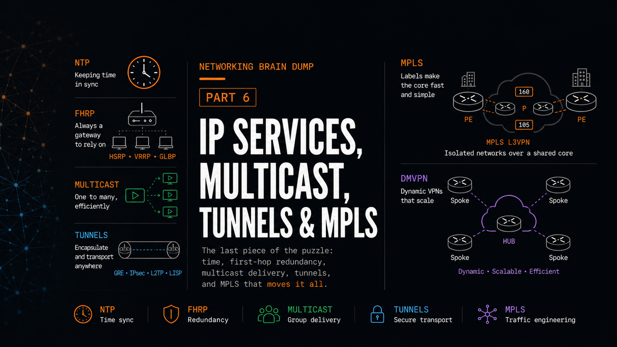
Part 6 of 6. This is the last one. It covers NTP, first-hop redundancy, multicast from IGMP through PIM, tunneling protocols, and MPLS including VPNs and DMVPN.
IP Services
NTP
NTP (Network Time Protocol) synchronizes clocks across network devices. It operates over UDP on port 123.
NTP gets its time from an authoritative source, typically an atomic clock, and distributes it outward. The distance from the authoritative source is described using stratums. A Stratum 1 server is directly connected to the atomic clock. A Stratum 2 server gets its time from a Stratum 1 server. A Stratum 3 server gets its time from Stratum 2, and so on. While devices generally prefer the neighbor with the lowest stratum number as their time source, they may also consider reachability, delay, dispersion, and overall source quality.
NTP peers act as both client and server to each other. They each synchronize to their respective upstream servers, then peer with each other to stay aligned. If one drifts slightly, the peer relationship pulls them back toward agreement. This keeps both accurate without requiring them to depend solely on a single upstream source.
FHRP
FHRP (First-Hop Redundancy Protocol) is the category name for protocols that allow multiple routers to appear as a single default gateway to hosts on a LAN. If the active router fails, another takes over without requiring any reconfiguration on end devices. FHRP implementations typically share a virtual IP address and a virtual MAC address that hosts use as their default gateway. The active router responds to traffic sent to that virtual address.
Three protocols fall under FHRP:
HSRP
HSRP (Hot Standby Router Protocol) is Cisco proprietary. One router is active and handles all traffic. One router is standby and takes over if the active fails. Any additional routers are in a listening state, ready to become standby if needed.
Hosts use the virtual IP and virtual MAC as their default gateway. The virtual MAC is tied to the active router's forwarding. When hosts send ARP requests for the gateway, the ARP reply contains the virtual MAC.
Election: Routers compare their configured priority values. Default priority is 100 for all routers. The highest priority wins. If priorities are equal, the highest IP address becomes active.
Preemption: By default, a router that comes online with a higher priority after an election will not take over from the current active router. You have to explicitly configure preemption for that to happen. Without it, the first router to win the election stays active even if a better candidate appears later.
Interface tracking: If the active router's uplink fails (an interface that isn't part of the HSRP group itself), HSRP won't detect that failure and the router stays active even though it can no longer reach upstream. Interface tracking solves this: you tell HSRP to monitor a specific interface, and if that interface's line protocol goes down, the router automatically decrements its HSRP priority by a configured amount. If preemption is enabled and the decrement drops the priority below another router's value, the other router takes over.
HSRPv2 adds support for IPv6.
VRRP
VRRP (Virtual Router Redundancy Protocol) is not Cisco proprietary and works across vendors. The active router is called the master. All others are backup routers.
VRRP enables preemption by default, unlike HSRP. The virtual IP address can be the same as the real IP address of one of the group members, and that router automatically becomes master without requiring a separate election.
VRRPv2 supports IPv4 only. VRRPv3 supports both IPv4 and IPv6.
GLBP
GLBP (Gateway Load Balancing Protocol) is Cisco proprietary and does something the other two don't: it allows multiple routers to actively forward traffic simultaneously rather than having one active and the rest idle.
One router in the group is elected as the AVG (Active Virtual Gateway). The AVG assigns a unique virtual MAC address to each group member and listens for ARP requests from hosts on the segment. When a host ARPs for the gateway, the AVG replies with the virtual MAC of one of the group members, cycling through them to distribute hosts across gateways. Each group member, called an AVF (Active Virtual Forwarder), forwards traffic sent to its assigned virtual MAC.
The AVG can assign itself a virtual MAC and act as an AVF as well. Up to 4 AVFs can be configured. If an AVF fails, the AVG assigns its virtual MAC to another AVF and stops advertising the failed MAC in ARP replies. Traffic naturally shifts as ARP caches expire and hosts receive new replies. If the AVG itself fails, the standby AVF with the highest priority takes over as the new AVG.
Multicast
Multicast is a one-to-many delivery mechanism. Instead of sending the same traffic to each receiver individually (unicast) or flooding it to everyone (broadcast), multicast delivers traffic to a group of interested receivers efficiently.
The IPv4 multicast address range is 224.0.0.0 through 239.255.255.255. At Layer 2, multicast frames are identified by a destination MAC address where the first 24 bits are 01:00:5E. A multicast MAC address is never used as a source address.
Switches, by default, treat multicast frames as unknown traffic and flood them out every port. IGMP snooping, covered below, is what fixes that.
IGMP
IGMP (Internet Group Management Protocol) is how receivers signal to their local router that they want to join or leave a multicast group.
When a receiver wants to join a multicast group, it sends an IGMP join message to the multicast group address. Its NIC is reprogrammed to accept frames destined for that group's Layer 2 address. The local router receives the join and knows there's a receiver on that segment interested in that group. It then sends a PIM join toward the source of that multicast traffic. When the router receives the multicast stream, it forwards it to the segment with the interested receiver.
Leaving works the same way in reverse: the receiver sends a leave message.
IGMP querier election: When more than one router is present on a segment, only one should send membership queries. The routers elect a querier: the router with the lowest interface IP address wins. The querier periodically sends membership queries to connected receivers to confirm they still want traffic. If the querier goes silent long enough for the querier timeout to expire, a new election takes place and another router takes over as querier. The exact timer depends on the IGMP version, platform, and configured query values, but usually this is 255 seconds (twice the default query interval).
IGMPv3 adds source-specific multicast capabilities. A receiver can signal membership to a group in one of two modes:
- Include mode: The receiver announces membership and provides a list of source addresses it wants traffic from. Traffic from sources not on the include list is dropped.
- Exclude mode: The receiver announces membership and provides a list of source addresses it does not want to receive traffic from. Traffic from all other sources is accepted.
IGMP snooping is how Cisco switches avoid flooding multicast traffic everywhere. The switch examines IGMP join messages as they pass through and builds a table mapping multicast groups to the specific interfaces where receivers have expressed interest. When a multicast frame arrives destined for a group, the switch forwards it only out the interfaces in that table, not every port.
PIM
PIM (Protocol Independent Multicast) is the protocol routers use between each other to build multicast distribution trees. It's "protocol independent" because it uses the existing unicast routing table to determine path selection rather than running its own routing protocol.
The core mechanism PIM relies on is RPF (Reverse Path Forwarding). To decide whether to accept and forward an incoming multicast packet, a router checks whether it arrived on the interface it would use to reach the source via unicast. If yes, the router accepts and forwards the packet. If no, the router discards it. This prevents duplicate traffic from circulating in loops.
Distribution tree terminology:
- Upstream: toward the source of the multicast traffic. The incoming interface is called the IIF (Incoming Interface).
- Downstream: toward the receivers. Outgoing interfaces are OIFs (Outgoing Interfaces). The full list of OIFs for a given group on a router is the OIL (Outgoing Interface List).
- LHR (Last Hop Router): the router directly connected to the receivers. Also called the leaf router.
Two types of distribution trees:
Source trees: The root of the tree is the multicast source itself. Branches extend outward through the network to each receiver following the shortest path. Routes in a source tree are identified by (S,G) notation, where S is the source address and G is the group address. Every router along the path maintains an S,G entry.
Shared trees: The root of the tree is a router designated as the Rendezvous Point (RP), not the source. All routers send joins toward the RP. Routes to the RP are identified by (*,G) notation, where the asterisk means "any source."
PIM Dense Mode
PIM Dense Mode assumes receivers are densely distributed throughout the network. It builds the distribution tree by flooding multicast traffic out every interface toward every PIM-enabled router in the network.
Routers that receive traffic but have no interested receivers send a PIM prune message back toward the source. The upstream router removes the pruned interface from its OIL. If a router is receiving the same multicast stream on two interfaces, it keeps the one on the RPF path and prunes the other.
Prunes expire after 3 minutes. When they expire, the traffic is reflooded and the prune-where-needed process repeats. Dense mode is appropriate when receivers genuinely are dense and the periodic reflooding overhead is acceptable.
PIM Sparse Mode
PIM Sparse Mode assumes receivers are scattered. It doesn't flood anything by default. Traffic only flows where receivers have explicitly requested it.
The flow, step by step:
- A receiver sends an IGMP join to its local router (the LHR).
- The LHR sends a (*,G) PIM join toward the RP.
- The RP notes that a receiver exists out the interface where it received the join. If a source is already active, the RP begins forwarding traffic down the tree. If no source is active yet, the RP stores the join and waits.
- When a source begins sending multicast traffic, its directly connected router encapsulates those multicast packets in a unicast packet and sends them as an S,G register message to the RP. Routers between the source and RP don't see multicast traffic and don't update their multicast routing tables.
- The RP decapsulates the register packets and forwards the traffic down the shared tree to the receiver.
- Simultaneously, the RP sends an (S,G) PIM join back toward the source. This builds a shortest-path tree from the source to the RP so that traffic can flow as native multicast rather than encapsulated unicast. Once that shortest-path tree is established, the RP sends a register stop message to the source's router, ending the unicast encapsulation.
- Traffic now flows as multicast from source to RP, and from RP to receiver.
- The LHR, which is now receiving multicast traffic, can see the source address directly. It sends an (S,G) PIM join directly toward the source, building a shortest-path tree from source to receiver that bypasses the RP entirely.
- The LHR then prunes itself from the shared tree through the RP. If the RP has no other receivers needing the traffic, it also prunes itself from the source.
The end state: traffic flows on the optimal shortest path from source to receiver with the RP no longer in the forwarding path.
PIM Assert
If a router detects that it's receiving multicast traffic on an interface it would normally use to forward that traffic (an outgoing interface), it means two routers are both forwarding the same multicast traffic onto the same segment. The PIM assert mechanism resolves which one stops.
The two routers exchange their routing information for the source: administrative distance first (lower wins), then metric (lower wins), then highest IP address as a final tiebreaker. The losing router prunes its outgoing interface for 3 minutes. After the prune expires, the process restarts if the condition still exists.
Rendezvous Point Discovery
Every router in a PIM Sparse Mode network needs to know where the RP is. Three options:
Static: Configure the RP address directly on every router. Simple. Doesn't scale well and creates a manual update problem when the RP changes.
Auto-RP (Cisco proprietary): Two roles: Candidate RPs (C-RPs) and RP Mapping Agents (MAs).
C-RPs advertise their willingness to serve as RP by sending RP-announce messages to the multicast address 224.0.1.39. Mapping agents listen to this address, collect the announcements, and elect the RP for each group (usually based on highest IP address). The MAs then multicast the RP-to-group mapping to 224.0.1.40. All Cisco routers running PIM listen to 224.0.1.40 and learn the RP from it.
C-RPs send announcements every 60 seconds. The MA hold time for C-RP entries is three times that by default, so 3 minutes. If a C-RP stops announcing, its entry ages out within 3 minutes and the MA re-elects.
BSR (Bootstrap Router) - non-proprietary: The BSR floods its presence hop-by-hop to all PIM-enabled routers using the all-PIM-routers address 224.0.0.16 with a TTL of 1. Each router forwards the BSR message out its PIM-enabled interfaces to its immediate neighbors.
Routers configured as Candidate BSRs (C-BSRs) receive these messages. The message contains the IP of the currently active BSR. C-BSRs compare and the one with the highest priority (or highest IP if priorities tie) wins and becomes the active BSR.
C-RP routers send unicast C-RP advertisement messages directly to the active BSR. The BSR collects these and floods the complete list of C-RPs to all routers in the domain. Each router then runs a hash algorithm using priority and IP address to determine which C-RP serves as RP for each group.
If a router running as C-RP goes down, the BSR stops including it in the list it floods. Routers recalculate and shift to the next RP automatically.
Tunnels
GRE
GRE (Generic Routing Encapsulation) is a tunneling protocol that encapsulates packets from a variety of network layer protocols inside IP packets. A GRE tunnel adds its own GRE header, then wraps the packet in a new outer IP header containing the source and destination tunnel endpoint addresses, allowing packets to be routed across the underlying network as ordinary IP traffic. GRE is frequently combined with IPSec to add encryption, since GRE itself provides no security.
One problem to watch for with GRE tunnels is recursive routing: if the tunnel's destination address is advertised into an IGP running over the tunnel, the router may try to route toward that destination via the tunnel itself. Since the tunnel is virtual and depends on the underlying IP path to the same destination, the router creates a loop trying to reach the endpoint through the endpoint. The fix is to ensure the tunnel destination is reachable only via the underlay, not via the tunnel interface.
LISP
LISP (Locator/ID Separation Protocol) solves a specific problem: devices, particularly virtual machines, get bound to locations by their IP addresses. When a VM moves to a different physical host or data center, its IP address changes, and everything that referenced the old address breaks.
LISP separates identity from location. Devices have EIDs (Endpoint Identifiers), their logical identity addresses. The network has RLOCs (Routing Locators), the addresses of the routers responsible for forwarding traffic to those EIDs.
xTR routers (tunnel routers at the network edge) register their EIDs and the RLOCs for those EIDs with a mapping server, which functions similarly to a DNS server. When a router needs to reach an EID, it queries the mapping server, gets back the corresponding RLOC, and forwards the packet to that RLOC. The xTR at the destination decapsulates and delivers to the EID.
When a device moves, the mapping server is updated with the new RLOC. The change propagates through the mapping system. No global routing protocol updates, no prefix changes, and no full routing reconvergence just because the endpoint moved. Existing sessions may still see a brief interruption. The route entries in every router in the network don't need to change.
MPLS
MPLS (Multiprotocol Label Switching) forwards packets based on short fixed-length labels rather than routing table lookups against IP destination addresses. In a traditional IP network, every router along the path performs a full routing table lookup for every packet. MPLS moves that work to the edges and replaces it with simple label operations in the core.
Key roles:
- LSR (Label Switching Router): Any router within the MPLS domain. Core routers that only swap labels.
- E-LSR / Edge LSR: Routers at the boundary of the MPLS domain. Ingress E-LSRs take unlabeled IP packets and impose a label. Egress E-LSRs receive labeled packets and pop the label before forwarding the original IP packet normally.
- LSP (Label Switched Path): The complete path a labeled packet takes through the MPLS domain, from ingress to egress.
Label Allocation
The process of building the label forwarding infrastructure:
- IP routing protocols build the standard routing table on each router as normal.
- Each LSR assigns a label to every destination in its routing table.
- LSRs advertise their assigned labels to all neighboring LSRs using a label distribution protocol.
- Every LSR builds three tables:
- LIB (Label Information Base): all labels received from neighbors.
- LFIB (Label Forwarding Information Base): the active forwarding table using labels.
- FIB (Forwarding Information Base): the standard IP forwarding table.
- Edge LSRs additionally store label information alongside their routing table entries so they know which label to impose on incoming unlabeled packets.
Forwarding
When an unlabeled IP packet arrives at an ingress E-LSR, the router checks its routing table, finds the entry, retrieves the associated label, imposes that label on the packet, and forwards it toward the next hop.
At each intermediate LSR, the router checks its LFIB using the incoming label, swaps it for the outgoing label that the next-hop LSR expects, and forwards the packet out the appropriate interface.
At the egress E-LSR, the router checks its LFIB, sees that it needs to pop the label, removes it, and then consults its routing table to forward the original IP packet to its final destination.
PHP (Penultimate Hop Popping): A small optimization. The egress E-LSR advertises an implicit null label to its upstream neighbor (the penultimate LSR). The penultimate router receives this label, recognizes it as implicit null, pops the label itself, and forwards the now-unlabeled packet to the egress E-LSR. The egress router receives a plain IP packet and only needs to check its routing table once, rather than checking the LFIB to pop the label and then checking the routing table. One fewer lookup per packet at the busiest point in the path.
MPLS VPNs
MPLS VPNs allow service providers to carry traffic for multiple customers over the same infrastructure while keeping each customer's routing table completely isolated from the others, even when those customers use overlapping address space.
VRF (Virtual Routing and Forwarding): Each customer gets its own routing table on the PE routers. VRF_A holds Customer A's routes. VRF_B holds Customer B's routes. Traffic arriving from a CE router is placed into the appropriate VRF and never crosses into another customer's table.
RD (Route Distinguisher): Even with separate VRFs, duplicate IP prefixes create a problem when PE routers need to exchange routes over the MPLS backbone: if Customer A and Customer B both use 192.168.1.0/24, those two routes are indistinguishable in BGP. A Route Distinguisher is prepended to each prefix to make it globally unique. Format is ASN:number or IP:number (e.g., 100:1). Customer A's route becomes 100:1:192.168.1.0/24. Customer B's becomes 100:2:192.168.1.0/24. Different routes, no collision.
RT (Route Target): Controls which VRFs import and export which routes. When a PE router exports a route from a VRF, it attaches a Route Target community. Other PE routers with VRFs configured to import that RT will pull the route into their local VRF. This allows flexible route sharing: a customer's Site 1 and Site 2 share the same RT so their routes flow between them, while another customer's routes carry a different RT and stay separate.
MP-BGP (Multiprotocol BGP): The control plane that exchanges VPN routes between PE routers. MP-BGP carries VPNv4 routes (RD-prefixed prefixes with RT attributes attached) across the MPLS core. Core P (provider) routers don't need to know anything about customer routes; they just swap labels. Only PE routers run MP-BGP.
MP-BGP also distributes the MPLS labels associated with each VPN route. This is the link between the control plane and the data plane: MP-BGP sets up the routing and hands out the labels, MPLS uses those labels to move the actual packets.
In some deployments, LDP (Label Distribution Protocol) runs between core P and PE (provider edge) routers to distribute labels for basic IP connectivity across the backbone. MP-BGP then adds VPN-specific labels on top of that. Other deployments can use different label distribution methods, but the basic idea stays the same: the core needs labels to move traffic across the backbone, and MP-BGP carries the VPN-specific route information between PE routers.
The complete flow for a VPN route:
- CE router (Customer Edge) advertises a prefix to its local PE router via IGP or static routing.
- The PE router places the route into the appropriate VRF, prepends the RD, and attaches the RT.
- The PE router advertises the resulting VPNv4 route to the remote PE via MP-BGP across the MPLS core.
- The remote PE receives the update, checks the RT, and imports the route into the matching VRF.
- The remote PE advertises the prefix to the remote CE via IGP.
- Customer traffic flows: CE → PE1 (label imposed) → P routers (label swapped) → PE2 (label popped and matched back to the correct VRF) → CE.
At no point do the core P routers know anything about 192.168.1.0/24. They only see labels.
DMVPN
DMVPN (Dynamic Multipoint VPN) is a Cisco technology that creates a hub-and-spoke VPN architecture where spokes can dynamically form direct tunnels to each other without those tunnels being pre-configured.
Two components make this work:
Multipoint GRE: Unlike a standard GRE tunnel that has both a fixed source and a fixed destination, a multipoint GRE tunnel has a source but no pre-configured destination. This allows the tunnel interface to serve as an endpoint for multiple different spoke tunnels simultaneously, using a single subnet for all of them.
NHRP (Next Hop Resolution Protocol): The hub router is configured as an NHRP next-hop server. Spoke routers are NHRP clients. When a spoke router connects, it registers its public IP address and its tunnel IP address with the hub's NHRP server. The server maintains a mapping table of tunnel IPs to public IPs for every registered spoke.
When a spoke needs to communicate with another spoke directly (rather than hairpinning through the hub), it queries the NHRP server at the hub asking for the public IP of the destination spoke. The hub replies with that public IP. The originating spoke can then initiate a direct GRE tunnel to the destination spoke because it now knows the peer address.
A concrete example: Router A is the hub and NHRP server. Routers B and C are spokes. Router C needs to send packets to Router B. C queries A asking for B's public IP. A replies with B's public IP. C establishes a direct GRE tunnel to B. That tunnel between the spokes is dynamic and exists only as long as traffic is flowing; it tears down/ages out when idle.
The key advantage over a traditional hub-and-spoke VPN is that spoke-to-spoke traffic doesn't have to traverse the hub at all once the dynamic tunnel is established. The hub handles the NHRP lookup but stays out of the data path after that.
That's the full series. Six parts, every major networking concept from how bits travel on copper to how MPLS moves packets across a provider core without the core routers needing to know the customer routes.
Part 6 of 6 in the Networking Brain Dump series.